This is the ONLY copy of this manual I could find for a realistic price. Even Panasonic could not provide me with one.
The PDF is a very good copy and it helped me diagnose and find the fault with the unit I have.
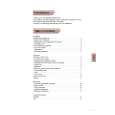
Text excerpt from page 3 (click to view)
2-2. SCHEMATIC DIAGRAM
TMR-IF330R
r
IC BLOCK DIAGRAM
ADJ ON/OFF
IC11 TA2061AF-EL
L-CH OUT AGC AUTO AGC T/C (R) F0 ADJ (L)
16
15 VREF
14
13 LEVEL DET.
12
11
10
9
Note: � All capacitors are in µF unless otherwise noted. pF: µµF 50 WV or less are not indicated except for electrolytics and tantalums. � All resistors are in � and 1/4 W or less unless otherwise specified. � % : indicates tolerance. � U : B+ Line. � H : adjustment for repair. � Power voltage is dc 9 V and fed with regulated dc power supply from external power voltage jack (J4). � Voltages are dc with respect to ground under no-signal conditions. � Voltages are taken with a VOM (Input impedance 10 M�). Voltage variations may be noted due to normal production tolerances. � Signal path. F : AUDIO J : RF
AGC
PRE EMPHASIS Lout = L + K � (L�R) Rout = R � K � (L�R)