|
|
|
Who's Online
There currently are 6043 guests online. |
|
Categories
|
|
Information
|
|
Featured Product
|
|
|
 |
|
|
There are currently no product reviews.
 ;
got exactly what i ordered in a very timely manner. will use again for other manuals
 ;
I'm happy. Good quality. Very helped me with my work..............................
;
This is the second Manual I have ordered from owner-manuals, I give it five stars because it is exactly what I expected given the age of the equipment. So the contents look a bit aged and the pictures a bit grainy, it fulfills my needs and I am glad I can still get hold of them.
;
thank u so much for this manual that was so cheap that i thought it was a scam but i gambled anyway because it was too good of a deal to pass up and behold,the manual has everything and details of everything even the screws and im still amazed and very happy with my manual .so take my word and jump on it before they realize how cheap they selling thier manuals..thank you so much for taking time to read my thoughts
;
I do not have very much to say.
The price is quite covenient, delivery was better as promised (about 12 ours, against the specified 24 hours if I remember well), and the quality of the PDF is more than acceptable.
The Service Manual of Sansui R30 itself is also satisfactory: good graphic for schematics and layouts, simple and well structured.
Giovanni Bianchi
11. Rotate the AMS knob until the waveform of the oscilloscope moves closer to the specified value. In this adjustment, waveform varies at intervals of approx. 2%. Adjust the waveform so that the specified value is satisfied as much as possible. (Traverse Waveform)
5-12. FOCUS BIAS ADJUSTMENT
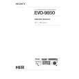
Adjusting Procedure : 1. Load a test disk (MDW-74/AU-1). 2. Rotate the AMS knob and display �CPLAY MODE� (S: 30). 3. Press the YES button and display �CPLAY MID�. 4. Press the MENU/NO button when �C = AD = � is displayed. 5. Rotate the AMS knob and display �FBIAS ADJUST� (S: 13). 6. Press the YES button and display � / a = �. The first four digits indicate the C1 error rate, the two digits after [/] indicate ADER, and the 2 digits after [a =] indicate the focus bias value. 7. Rotate the AMS knob in the clockwise direction and find the focus bias value at which the C1 error rate becomes 220 (Refer to Note 2). 8. Press the YES button and display � / b = �. 9. Rotate the AMS knob in the counterclockwise direction and find the focus bias value at which the C1 error rate becomes 220. 10. Press the YES button and display � / c = �. 11. Check that the C1 error rate is below 50 and ADER is 00. Then press the YES button. 12. If the �( )� in � ( )� is above 20, press the YES button. If below 20, press the MENU/NO button and repeat the adjustment from step 2. 13. Press the §EJECT button to remove the test disc. Note 1 : The relation between the C1 error and focus bias is as shown in the following figure. Find points a and b in the following figure using the above adjustment. The focal point position C is automatically calculated from points a and b. Note 2 : As the C1 error rate changes, perform the adjustment using the average vale.
C1 error
A VC B
Specification A = B
12. Press the YES button, and save the adjustment results in the non-volatile memory. (�EFB = SAV� will be displayed for a moment.) Next �EF MO ADJUS� is displayed. The disc stops rotating automatically. 13. Press the §EJECT button and remove the disc. 14. Load the check disc (MD) TDYS-1. 15. Roteto AMS knob and display �EF CD ADJUS� (S: 12). 16. Press the YES button and display �EFB = CD�. Servo is imposed automatically. 17. Rotate the AMS knob so that the waveform of the oscilloscope moves closer to the specified value. In this adjustment, waveform varies at intervals of approx. 2%. Adjust the waveform so that the specified value is satisfied as much as possible. (Traverse Waveform)
A VC B
220
Specification A = B
18. Press the YES button, display �EFB = SAV� for a moment and save the adjustment results in the non-volatile memory. Next �EF CD ADJUS� will be displayed. 19. Press the §EJECT button and remove the check disc (MD) TDYS-1. Note 1 : MO reading data will be erased during if a recorded disc is used in this adjustment. Note 2 : If the traverse waveform is not clear, connect the oscilloscope as shown in the following figure so that it can be seen more clearly.
Oscilloscope
b
c
a
Focus bias value (F. BIAS)
BD board CN110 pin 3 (TEO) CN110 pin 1 (VC)
330 k� 10pF
� 47 �
|
|
|
> |
|