Shopping cart is empty
 
English Polski Spanish 
Search For a Manual
 

(e.g. AA-V20EG JVC, ZX-7 Sony )
PayPal 1000+ rating Secure, Encrypted Checkout.
 
Who's Online
There currently are 5949 guests online.
Categories
Information
Featured Product
Home >> SONY >> CDXM700R Service Manual
 
 0 item(s) in your cart 

SONY CDXM700R
Service Manual


Tweet about this product and get $1.00 of store credit for instant use!
  • Contains Circuit Diagrams
  • Download
  • PDF Format
  • Complete manual
  • Language: English
Price: $4.99

Description of SONY CDXM700R Service Manual

Complete service manual in digital format (PDF File). Service manuals usually contains circuit diagrams, printed circuit boards, repair tips, wiring diagrams, block diagrams and parts list. Service Manual ( sometimes called Repair Manual ) is used mainly by technicians.

If You just want to know how to use Your tv, video, mp3 player etc. You should look for Owner's Manual. After placing order we'll send You download instructions on Your email address.

The manual is available in languages: English

Not yet ready
You must purchase it first

Table of Contents
    1. GENERAL
      • Location of Controls
      • Getting Started
      • Setting the Clock
      • CD Player CD/MD Unit
      • Radio
      • RDS
      • DAB
      • DSP
      • Other Functions
      • TV/Video
      • Connections
    1. DISASSEMBLY
      1. Front Panel Assy (Normal)
      2. Front Panel Assy (Inoperative)
      3. CD Mechanism Block, Flexible Board
      4. Sub Panel (CD) Sub Assy
      5. Motor Block Assy, Cam (R) Assy
      6. Main Board
      7. Heat Sink
      8. Chassis (T) Sub Assy
      9. Lever Section
      10. Servo Board
      11. Shaft Roller Assy
      12. Floating Block Assy
      13. Optical Pick - up Block
    2. PHASE ALIGNMENT
      1. Arm (A - L) Assy, Arm (B - L) Assy
      2. Cam (L)
      3. Motor Block
      4. Alignment Between Arm (A - L) Assy and Arm (B - L) Assy
      5. Arm (A - R) Assy, Arm (B - R) Assy
      6. Cam (R)
    3. DIAGRAMS
      1. IC Pin Descriptions
      2. Block Diagram - CD Section
      3. Block Diagram - Tuner Section
      4. Block Diagram - Display Section
      5. Circuit Boards Location
      6. Printed Wiring Boards - CD Mechanism Section
      7. Schematic Diagram - CD Mechanism Section (1/2)
      8. Schematic Diagram - CD Mechanism Section (2/2)
      9. Printed Wiring Boards - Main Section
      10. Schematic Diagram - Main Section (1/4)
      11. Schematic Diagram - Main Section (2/4)
      12. Schematic Diagram - Main Section (3/4)
      13. Schematic Diagram - Main Section (4/4)
      14. Printed Wiring Board - Sub Section
      15. Schematic Diagram - Sub Section
      16. Printed Wiring Board - Display Section
      17. Schematic Diagram - Display Section
    4. EXPLODED VIEWS
      1. Chassis Section
      2. Front Panel Section
      3. CD Mechanism Section (1)
      4. CD Mechanism Section (2)
      5. CD Mechanism Section (3)
    5. ELECTRICAL PARTS LIST
Customer Reviews
There are currently no product reviews.
Other Reviews
 KX-880HX KENWOOD Service Manual by Hartmut Lachenmann;
The Manual was perfect. The deliverie was perfect. Thanks
 TX32PB50D PANASONIC Service Manual by DAVID SHEPHERD;
Found website easy to use and manual very clear. First class service
 SUV65A TECHNICS Service Manual by Angelo-Marco Farina;
The quality is quite good and clear. Nothing of the informations inside is lost during the digitalizing process
 STR-1800 SONY Service Manual by Peter Ramaekers;
Very good service, fast downloads and good manuals.
 SLV815U/V SONY Service Manual by Xavier Carol;
Good qulity. Even as it is an old manual (from 1991-1992) it has a good scanned quality and is complete, including user's manual, disassembly intructions, diagrams and schematics, ajustments, troubleshooting and parts list, as usual with SONY manuals and Owner-manuals service.

Text excerpt from page 29 (click to view)
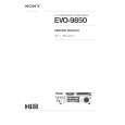
SECTION 3 PHASE ALIGNMENT
3-1. ARM (A-L) ASSY, ARM (B-L) ASSY

4 arm (A-L) assy

5 stop ring 1.5, type-E

2 stop ring 1.5, type-E 1 arm (B-L) assy

3 spring (arm L)

bracket (L) assy

3-2. CAM (L)
1 Move the arm (B-L) assy in the direction of the arrow A and the arm (A-L) assy in the direction of the arrow B fully (full open state). 2 Align the hole on the cam (L) with part C and install the cam. 4 Turn the cam (L) clockwise and counterclockwise to verify that both the arms are operated. 3 stop ring 1.5, type-E

hole

cam (L)

C

A

arm (B-L) assy arm (A-L) assy B

29

You might also want to buy

$4.99

SX-K700 TECHNICS
Owner's Manual

Complete owner's manual in digital format. The manual will be available for download as PDF file aft…

$4.99

CJ-V51 PIONEER
Service Manual

Complete service manual in digital format (PDF File). Service manuals usually contains circuit diagr…

$4.99

GRAND PRIX ELECTRONIC 754 BECKER
Service Manual

Complete service manual in digital format (PDF File). Service manuals usually contains circuit diagr…

$4.99

SX-PR602 TECHNICS
Service Manual

Complete service manual in digital format (PDF File). Service manuals usually contains circuit diagr…

$4.99

EV-S1000E SONY
Owner's Manual

Complete owner's manual in digital format. The manual will be available for download as PDF file aft…

$4.99

GRAND PRIX ELECTRONIC 780 BECKER
Service Manual

Complete service manual in digital format (PDF File). Service manuals usually contains circuit diagr…

$4.99

AG7330 PANASONIC
Service Manual

Complete service manual in digital format (PDF File). Service manuals usually contains circuit diagr…

$4.99

EVO-9850 VOLUME 1 SONY
Service Manual

Complete service manual in digital format (PDF File). Service manuals usually contains circuit diagr…
>
Parse Time: 0.262 - Number of Queries: 128 - Query Time: 0.073